‘Design for Reliability’ in power electronics with new interconnection technologies for future smart mobility and smart energy solutions


New solutions for use of electrical energy require increased power density for energy efficiency
The increase in the permissible operating peak temperatures is an important prerequisite for increasing the efficiency in power electronics modules and thus the energy efficiency of the electric drives and power steering. However, for use of power electronic components it may come to local peak temperatures above 175 °C, which can no longer be controlled with soft solders. New materials for interconnects are required. Silver sintering is a promising new technology for interconnection purposes in power applications which allows high operating temperatures of the interconnects. This type of interconnection technology can be applied already for silicon semiconductors; however, if new high-temperature resistant semiconductors like SiC and GaN come into use there will be an absolute need for these interconnects. Development of these interconnection technologies and experimental and theoretical studies on their reliability were subjects of the BMBF-funded project »PROPOWER«. In the department MMC, the focus was on theoretical analysis of thermo-mechanical reliability risks that have been carried out using the finite element method (FEM).
Use of new materials for electronic systems and their interconnections means knowledge of new failure risk and design rules
Thermally induced stress due to thermal mismatch between the chips stacked between metallic and ceramic layers is generally the source for thermo-mechanical failure. Introduction of a new interconnect material means at the same time introduction of a new constitutive behavior and new failure modes. As the material stiffness increases, the decoupling effect of compliant solder layers reduces and intrinsic mechanical stresses increase in the whole power stack. This leads on one hand to less low cycle fatigue in the interconnect, as plastic dissipation is reduced, but to higher failure risks like brittle cracking and sub-critical crack growth. However, if early brittle failure can be avoided by appropriate designs, the new interconnection technology allows an increase in fatigue reliability of several hundred percent.
Optimal functional, mechanical, electrical and thermal design becomes key for competitive products
Two kinds of temperature loadings are essential for power electronic systems: passive thermal cycling, reflecting environmental temperature changes and active power cycling, i.e. power on/off. Both, passive and active thermal cycling, were investigated for power IGBT on DBC substrate with copper bonding technology. FE-analyses revealed that the stress loadings are different for passive and active cycling and hence, different failure modes have to be expected.
Active thermal cycling is most relevant for use condition in field. Different power cycling conditions were studied by FEA to understand the transient stress regime in the assembly. To obtain a realistic result comparable to testing, in particular to include the heat dissipation along the current path through the stack, fully coupled electrical, thermal and mechanical analyses were made.
Only these numerical multi-field simulations based on sophisticated material- and damage modeling can make the goal of »first time right« a reality during the design phase
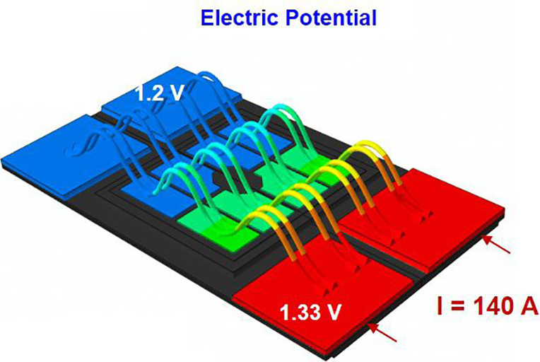
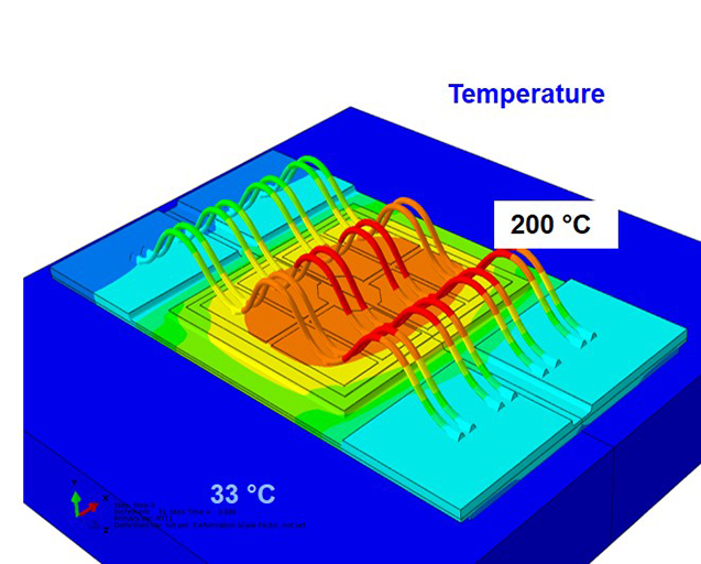
Starting from the electrical model with voltage distribution in the metallization and bonding wires, as exemplified in figure 1, the current distribution is calculated, which allows coupled calculations of the transient temperature distributions at each state of the active cycle, as shown for the end of an active cycle in figure 2. In the electric model switching losses and conduction and component characteristics, which result in Joule heating, are considered. Coupling of the transient temperature fields to mechanical stress simulations are performed after, an example given in figure 3. Based on this complex theoretical framework simulation results are validated by testing in order to achieve trustworthy thermo-mechanical reliability predictions. These highest standards allow the link to establish design rules for the new technology.
 Fraunhofer Institute for Electronic Nano Systems