Algorithms for the monitoring system ASTROSE® for increasing the current carrying capacity of overhead power lines


The self-sufficient sensor network ASTROSE® was developed in a research project and has been used in a pilot test with 59 sensor nodes since September 2014 on a 110 kV overhead power line in the Harz mountains in Germany. Each sensor node measures the temperature, the inclination of the conductor and the current flowing through the conductor. The measurement data is transmitted by radio from sensor node to sensor node to the base station. In the past, the data were used to evaluate the system for technical robustness and reliability. In order to achieve a commercial benefit by the application of such monitoring systems, the evaluation and further processing of the sensor data is necessary. The above mentioned measurement data primarily reflect the temperature of the conductor, the sag, the tensile force of the conductor and further mechanical loads if they derive from ice loads as an example. Moreover, the combination and fusion of measurement data and environmental condition data allow to determine the power line ampacity online.
Recently, a software module was developed together with the Fraunhofer IZM, which determines the cable temperature of each span field and the ampacity of the power line. This enables the grid operator to detect weak points in the grid (e.g. span fields with a too high cable temperature) and to exploit the reserves that arise in the energy transmission net depending on current weather conditions. The developed software module is currently in the evaluation phase. During this development and evaluation an indication parameter for the data reliability is transmitted in addition to the measurement data to the grid control centre which indicates particular situations that may lead to misinterpretation of the sensor data.
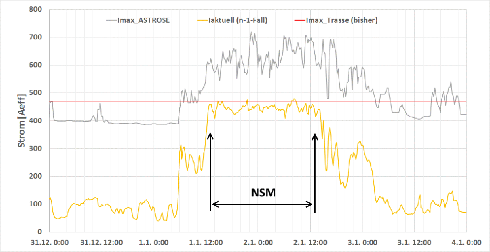
The first tests and data reviews show that the actual ampacity is much higher than the maximum rated ampacity of the overhead line. Shut down or the reducing of the power generation of wind power stations as part of the network security management measures could have been prevented. The figure on the left page shows such situation as an example. The rated maximum current is given by the red line in the diagram. The (n-1)-current (yellow curve) is calculated based on the actual grid situation by the grid control centre. It is the maximum current that may occur if one mayor component of the power grid fails. The grid control centre regulates the sources and the load such way that the (n-1)-current is always below the rated maximum current. The diagram show a sudden rising load on January 1st 12:00 pm that is limited to the rated maximum current by the grid control centre as part of the network security management till January 2 12:00 pm. Such kind of relief measures are regularly done by reduction of the power of wind power plants. The monitoring system indicates that it is more than 100 A higher than the rated maximum current of the power line in the period of time between January 1st and January 2st that is caused by chilling of the conductors due to strong wind. In case of the given example, the power relief would not have been extended that way.
 Fraunhofer Institute for Electronic Nano Systems